
 English
 Spanish
 French
 German
 Italian
 Chinese (Simplified)
 Japanese
 Korean
 Arabic
 Portuguese

 Send Inquiry
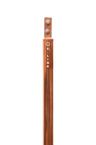
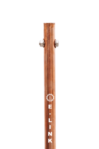
COPPER BONDED EARTHING ROD
Price 1809 INR/ Meter
COPPER BONDED EARTHING ROD Specification
- Diameter
- 48MM Millimeter (mm)
- Life Span
- 20 YEARS OF SAFETY
- Purity
- 99%
- Strength
- NA
- Product Type
- EARTHING
- Material
- Pure Copper
- Application
- EARTHING
- Function
- EARTHING SAFETY
- Shape
- ROUND
- Surface Treating
- COPPER COATING
- Dimension (L*W*H)
- 48MM *3 MTR Millimeter (mm)
- Weight
- 18 KG Kilograms (kg)
- Color
- copper
- Warranty
- 1 YEAR
COPPER BONDED EARTHING ROD Trade Information
- Minimum Order Quantity
- 1 Set
- FOB Port
- nahvasehva /hazira
- Supply Ability
- 300 Sets Per Day
- Delivery Time
- 3 Days
- Packaging Details
- BUBBLE PACKING
- Main Domestic Market
- All India
About COPPER BONDED EARTHING ROD
Earthing electrodes also known as grounding electrodes are crucial components in electrical systems designed to provide a safe path for electrical currents to dissipate into the ground They are essential for protecting people equipment and structures from electrical faults lightning strikes and static discharge Heres an overview of earthing electrodes
Purpose of Earthing Electrodes
1 Safety Prevent electric shock by providing a lowresistance path for fault currents to flow into the earth
2 Equipment Protection Safeguard electrical appliances and systems from damage due to overvoltage or lightning strikes
3 Stabilize Voltage Maintain a stable reference voltage for electrical systems
4 Dissipate Static Charges Prevent the buildup of static electricity in industrial and sensitive environments
Types of Earthing Electrodes
1 Rod Electrodes
Made of copperbonded steel galvanized iron or solid copper
Driven vertically into the ground
Commonly used in residential and commercial installations
2 Plate Electrodes
Made of copper or galvanized iron
Buried vertically or horizontally in the ground
Provide a large surface area for better conductivity
3 Pipe Electrodes
Made of galvanized iron or steel pipes
Filled with alternating layers of charcoal and salt to improve conductivity
4 Strip or Wire Electrodes
Made of copper or galvanized steel stripswires
Buried horizontally in trenches
Often used in areas with rocky or hard soil
5 Chemical Electrodes
Use conductive compounds or backfill materials to enhance soil conductivity
Ideal for areas with high soil resistivity
6 Grounding Mats
Made of conductive materials like copper or aluminum
Used in substations power plants and sensitive equipment areas
Factors Affecting Earthing Electrode Performance
1 Soil Resistivity Lower resistivity improves grounding efficiency
2 Electrode Material Highconductivity materials like copper are preferred
3 Depth of Installation Deeper electrodes often provide better grounding
4 Moisture and Temperature Wet soil and stable temperatures enhance conductivity
5 Electrode Size and Shape Larger surface area improves grounding
Installation Guidelines
1 Location Install electrodes in areas with low soil resistivity and adequate moisture
2 Spacing Maintain sufficient distance between multiple electrodes to avoid overlapping resistance zones
3 Connection Use proper clamps and connectors to ensure a secure and lowresistance connection to the grounding system
4 Testing Regularly test the grounding system to ensure its resistance meets safety standards typically below 5 ohms for most applications
Standards and Codes
IEC 60364 International standard for electrical installations
IEEE 80 Guide for safety in AC substation grounding
NEC National Electrical Code Provides guidelines for grounding in the US
IS 3043 Indian standard for earthing practices


Price:
- 50
- 100
- 200
- 250
- 500
- 1000+

More Products in Earthing Electrode Category
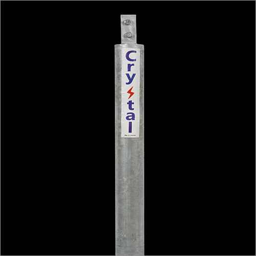
GALVANIZED EARTHING ELECTRODE
Price 1500.00 INR / Kit
Minimum Order Quantity : 1 Set
Shape : ROUND
Weight : 18 KG Kilograms (kg)
Material : Galvanized Steel
Color : SILVER
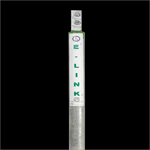
E LINK COPPER COATED EARTHING ROD
Price 5494.0 INR / Number
Minimum Order Quantity : 1 Set
Shape : ROUND
Weight : 30kg Kilograms (kg)
Material : Pure Copper
Color : COPPER
E LINK GALVANIZED EARTHING ELECTRODE
Price 4600 INR / Piece
Minimum Order Quantity : 1 Set
Shape : ROUND
Weight : 18 KG Kilograms (kg)
Material : Galvanized Steel
Color : SILVER
E LINK COPPER COATED EARTHING ROD
Price 6435 INR / Meter
Minimum Order Quantity : 10
Shape : ROUND
Weight : 18 Kilograms (kg)
Material : Pure Copper
Color : copper
Advanced Chemical Earthing
- No. 17/316, Shastri Nagar, Khatodara Colony,Surat - 395002, Gujarat, India
- Phone :08045800207
- Mr Naresh Ramavat (Partner)
- Mobile :08045800207
-
 Send Inquiry

 Send Inquiry
 Send SMS
Developed and Managed by Infocom Network Private Limited.

